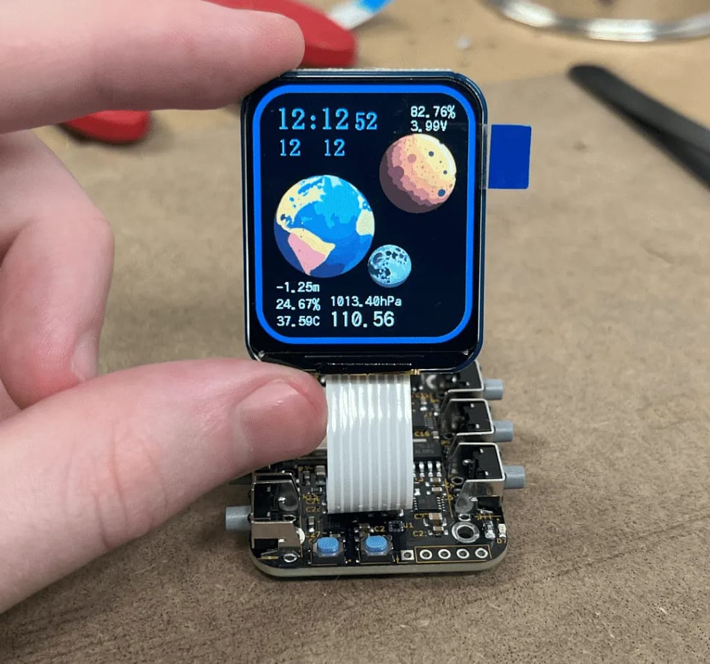
This open-source smartwatch project is built around the ESP32-S3 platform and provides a complete hardware–software development workflow, including schematic design, PCB layout, firmware development, and system debugging. The watch integrates wireless communication, environmental sensing, motion detection, distance measurement, and customizable user interaction, making it suitable for a wide range of engineering applications such as IoT control, environmental monitoring, prototyping, and academic research.
The project is particularly valuable for:
- Developers and hardware engineers exploring ESP32-S3–based systems
- Students advancing their embedded programming and sensor-integration skills
- Senior-year engineering majors preparing capstone or graduation projects
- Makers interested in custom wearables and low-power wireless devices
Through this project, users can learn practical skills including embedded C/C++ development, ESP-IDF workflows, sensor fusion, real-time data acquisition, PCB design, and short-range wireless protocols.


The smartwatch combines a dual-core ESP32-S3 MCU with a set of integrated sensors, a LiDAR ranging unit, a visible-light laser pointer, and a multi-button user interface. A four-layer PCB structure ensures stable signal integrity and compact component placement. The firmware is based on ESP-IDF and incorporates ESP-NOW for low-latency peer-to-peer communication.
Core system layers include:
- Processing Layer: ESP32-S3 handles sensor sampling, wireless communication, and UI control.
- Sensing Layer: BME680 (environment), ICM-42670 (motion), VL53L1X (ToF ranging).
- Interaction Layer: Five physical buttons supporting both single-action and combination shortcuts.
- Communication Layer: ESP-NOW for direct IoT device control without routers.
- Power Layer: LiPo battery with optimized sleep–wake cycles for extended runtime.

Hardware Specifications
| Component | Model | Key Specifications | Description |
|---|---|---|---|
| Main MCU | ESP32-S3 | Dual-core 32-bit LX7, Wi-Fi 2.4GHz, Bluetooth LE, USB OTG | Primary control unit handling computation, wireless stack, and peripherals |
| LiDAR Sensor | ST VL53L1X | 940nm IR ToF, ~4cm–4m range, mm-level repeatability | Time-of-flight distance measurement for short–medium range applications |
| Laser Pointer | 650nm diode | 5 mW, visible red light | Used for alignment and distance-point indication |
| Environmental Sensor | BME680 | Temperature, humidity, pressure, gas resistance | Measures environmental parameters and supports IAQ estimation |
| Motion Sensor | ICM-42670 | 6-axis IMU (3-axis gyro + 3-axis accel) | Tilt detection, leveling, motion-triggered wake functions |

Wireless & Communication
| Protocol / Module | Specification | Description |
|---|---|---|
| ESP-NOW | Latency typically <10ms, AES encryption, peer-to-peer | Direct device communication without router, supports 1-to-1 and 1-to-many |
| Wi-Fi (ESP32-S3) | 802.11 b/g/n (2.4 GHz) | Used for provisioning, diagnostics, OTA, and general connectivity |
PCB & Mechanical
| Item | Specification |
|---|---|
| PCB Layers | 4 layers (dual ground planes) |
| Dimensions | 43 × 36 mm |
| Design Notes | High-density component placement with inner-layer shielding for signal integrity |

ESP-NOW IoT Control
The smartwatch uses ESP-NOW to achieve low-latency and low-power wireless transmission. Unlike conventional Bluetooth, ESP-NOW operates at the data-link layer with a highly lightweight packet format, enabling:
- Direct peer-to-peer communication
- Broadcast-style control for multiple devices
- Sub-10 ms response time under typical conditions
- AES encryption with ECDH pairing for secure exchanges
This allows the watch to control DIY smart locks, LED systems, or home-automation nodes without a router—something commercial smartwatches typically cannot offer due to locked wireless stacks.
To reduce power consumption, the firmware activates Wi-Fi hardware only during transmit/receive cycles. The module automatically enters sleep mode after 1.5 seconds of inactivity, while the ICM-42670 IMU provides tilt-based wake detection. This hybrid strategy significantly improves battery longevity.

Sensor Subsystem
5.1 Distance Measurement (VL53L1X)
The VL53L1X uses a 940 nm IR VCSEL emitter and a SPAD array detector to calculate distance based on time-of-flight. Advantages include:
- Eye-safe IR wavelength
- Stable ranging from ~4 cm to 4 m
- Millimeter-level repeatability in short-range operation
- High resistance to ambient light interference
The onboard visible 650 nm pointer is used only for visual alignment, as the LiDAR emitter itself is invisible to the human eye.
Environmental Monitoring (BME680)
The BME680 integrates four sensing capabilities:
- Temperature
- Relative humidity
- Barometric pressure
- Gas resistance (VOC-sensitive layer)
IAQ scoring relies on Bosch’s BSEC algorithm, which estimates indoor air quality based on VOC trends, humidity baseline deviation, and long-term compensation. When combined, the watch offers meaningful insights for indoor comfort optimization.
Motion & Orientation (ICM-42670)
The IMU supports:
- Gyroscope + accelerometer sampling
- Tilt and leveling measurement
- Motion-triggered wake events
- Single-tap detection modes
The watch can be placed on a surface to perform slope or level calibration, useful for equipment alignment, DIY installation, or structural positioning tasks.
User Interaction & UI Logic
Five physical buttons provide complete control without relying on touch input—ideal for embedded debugging and field environments.
Core Button Functions
- Button 1 (Home): Wake the device / return to watch face
- Button 3: Toggle IMU mode / display MAC address
Combination Shortcuts
- Hold Button 4 + tap Button 1: Activate screen flashlight
- Hold Button 5 + tap Button 1–3: Send predefined ESP-NOW control commands
Advanced Features
- Long-press Button 1 + Button 2: Activate LiDAR ranging
- Long-press Button 1 + Button 3: Enable visible laser pointer
- Hardware reset button: Quick recovery from system anomalies
The firmware supports multiple visual themes, allowing users to switch display styles based on preference or environment.
Assembly Notes & Debugging Procedure
Schematic and Hardware Considerations
The main circuit integrates:
- ESP32-S3
- Sensor suite (VL53L1X, BME680, ICM-42670)
- Laser driver
- LiPo battery module
- Button interface circuit
A two-layer PCB would not support the high-density layout and routing complexity, hence a four-layer stack with internal ground planes was selected to reduce EMI and provide cleaner sensor readings.
Firmware Flashing and Initial Bring-Up
- Connect via USB-C and flash the firmware using ESP-IDF.
- If the display does not respond, perform a reset or power-cycle.
- Verify that serial logs show correct boot messages.
Functional Validation
- Wi-Fi scanning: Verify SSID, RSSI, and encryption mode.
- LiDAR ranging: Ensure stable readings across near and far targets.
- Environmental sensing: Compare values against known room conditions.
- IMU data: Check tilt accuracy and wake-on-motion behavior.
Final Assembly
After validation:
- Install the LiPo battery
- Enclose the board in a 3D-printed ABS housing
- Perform a final full-function test
ABS is recommended for durability and heat resistance.

Recommended Expansion Paths
The smartwatch platform is highly modular and can be expanded in several directions.
Communication Upgrades
- Add a LoRa transceiver for long-range control
- Transition to ESP32-C5 in future designs for 5 GHz Wi-Fi support
Additional Sensors
- Add an RFID module for access control
- Integrate a thermal imaging sensor (e.g., 32×24 grid) for temperature mapping
Interaction Enhancements
- Replace physical keys with a capacitive touch panel
- Add an external camera for low-resolution live monitoring
Positioning & Navigation
- Integrate GPS + magnetometer
- Provide direction, guidance and coordinate logging
Open-Source Resources
You can access the full project materials through the following repositories:
- Complete schematics and hardware documentation: RoboticWorx official guides
- BOM and component list: GitHub repository
- Source code and ESP-IDF firmware: GitHub codebase
Based on materials provided by RoboticWorx.