The Nintendo WaveBird wireless controller—released in 2002—was widely regarded as the gold standard for untethered gameplay in the GameCube era. Using a proprietary 2.4 GHz RF system rather than infrared, it offered an official range of 6 m and real-world performance exceeding 20 m, with up to 100 hours of playtime from two AA batteries. It remains a cherished piece of retro hardware for many enthusiasts.
Nintendo discontinued WaveBird production more than a decade ago. Original receivers have become scarce and second-hand prices have climbed to USD 50–80. The WavePhoenix open-source project offers a solution: a faithful receiver reproduction costing under USD 5 to build, with modern enhancements that bring the classic controller back to life.
WavePhoenix: Key Features
| Core Capability | Description |
|---|---|
| Protocol Compatibility | Fully reverse-engineered and reimplemented WaveBird proprietary protocol (15-chip DSSS + BCH error correction). Achieves 100% compatibility with original controllers. |
| Chip Platform | Silicon Labs EFR32BG22 wireless SoC — widely available from major distributors at approx. USD 3–4. |
| Hardware Design | Open-source PCB (KiCad/Gerber provided). Receiver is ~1/3 the footprint of the original, improving portability. |
| Pairing Method | Virtual pairing: long-press X + Y on the controller to auto-scan all 16 channels — no mechanical dial required. |
| Feature Enhancements | Status LED (pairing/communication), Bluetooth OTA firmware updates, support for custom 3D-printed enclosures. |
| Cost Efficiency | Total BOM cost < USD 5. DIY-friendly or purchasable via community vendors; significantly cheaper than legacy originals. |
| RF Performance | Maintains 2.4 GHz RF behavior with stable >20 m real-world range and negligible latency. |
Extended Advantages
1. Expanded Compatibility
WavePhoenix supports GameCube consoles and Wii systems running GameCube mode. It is also compatible with emulators such as Dolphin and works with PC/Raspberry Pi retro-gaming setups without extra adapters.
2. Active Community Ecosystem
The GitHub repository receives regular firmware updates (roughly quarterly). The community provides documentation, troubleshooting guides, custom 3D-print files, and mod accessories like extended cables.
3. Sourcing Recommendations
- Select RF-BM-BG22C3 modules from reputable suppliers to avoid RF instability.
- Use 1.6 mm FR-4 PCB with hole tolerances ±0.1 mm for reliable connector fit.
- Prefer gold-plated JST-SH headers and GameCube male connectors to improve contact longevity.

Hardware Overview and Complete BOM
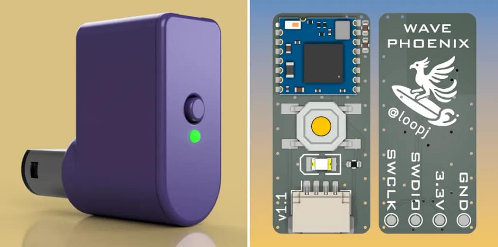
The WavePhoenix mini-receiver is a compact adapter centered around the RF-BM-BG22C3 module, with minimal power filtering, a pairing switch, a status LED, and a JST-SH connector. The design goal is low cost and easy assembly, allowing beginners to build a working receiver quickly.
| Component | Specification | Qty | Notes |
|---|---|---|---|
| Wireless Module | RF-BM-BG22C3 | 1 | Prefer module with built-in antenna to simplify tuning. |
| Status LED | 0805 Green | 1 | Color optional; function unaffected. |
| Pairing Button | 5×5 mm tactile switch | 1 | Pick moderate actuation force for better feel. |
| Connector | 4-pin JST-SH | 1 | Housings with triangle orientation mark recommended. |
| Current-Limiting Resistor | 0402 100 Ω | 1 | Protects LED; value can be tuned for brightness. |
| Filter Capacitor | 0402 10 µF | 1 | Recommended for stable power rail. |
| HF Bypass Capacitor | 0402 0.1 µF | 1 | Reduces RF noise; improves reliability. |
| GameCube Plug | Male Connector | 1 | Choose version with latch for mechanical security. |
| Light Guide | 1.5 mm PMMA fiber | 1 | Cut to ~4 mm; or use similar light pipe. |
| Wiring Harness | Pre-crimped cable set | 1 set | At least 3 wires (VCC / GND / DATA); recommended length 30 mm. |
Tools required: Crimping tool, fine-tip soldering iron, magnifier, wire cutters, small file for housing, optionally a 3D printer (or source a ready-made case).
Assembly steps:
- Cable prep: Cut JST-SH cable to ~30 mm. Strip 1 mm insulation and crimp to the GameCube connector pins in order: Pin 1 = VCC (red), Pin 2 = DATA (blue), Pin 3 = GND (black). Verify orientation mark on the connector.
- Firmware flash: Perform initial flashing as described below. After successful bootloader install, OTA updates are available.
- Mechanical assembly: Snap the GameCube plug into the case until it clicks, connect JST-SH to PCB, align LED and switch to the case openings, seat PCB.
- Light-pipe fit: Insert PMMA fiber for LED indicator alignment.
- Final check: Install button, close case, verify no loose parts.
Soldering tips:
- Solder order: RF module → capacitors/resistors → LED → switch.
- For 0402 components: set iron 320–350 °C, tack one pad then align and solder opposing pad.
- If 10 µF / 0.1 µF are difficult to solder, the device may function but power stability and RF performance could suffer over long-term use.

Full Firmware Flashing Guide
Prerequisites
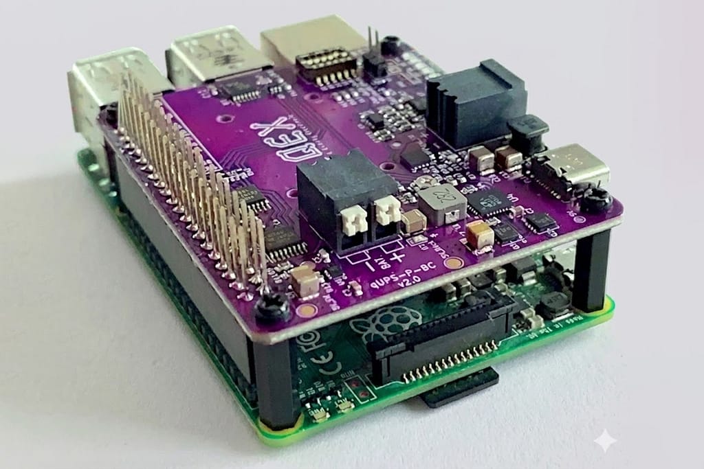
- SWD-capable debug probe (Raspberry Pi Pico can be used as a probe—see Appendix).
- Arduino-patched OpenOCD supporting EFR32 Series 2.
- Firmware releases: bootloader and receiver firmware (select rf-bm-bg22c3).
Important: After device erase, disconnect and reconnect the probe before proceeding to flashing steps.
Device Erase (mandatory for first flash)
Linux / macOS
openocd
    -f "interface/cmsis-dap.cfg" \
    -f "target/efm32s2.cfg" \
    -c "init; efm32s2_dci_device_erase; shutdown"
Windows (PowerShell)
openocd.exe
    -f "interface\cmsis-dap.cfg" `
    -f "target\efm32s2.cfg" `
    -c "init; efm32s2_dci_device_erase; shutdown"
Flash Bootloader
After this step, you can update firmware via Bluetooth OTA.
Linux / macOS
openocd
    -f "interface/cmsis-dap.cfg" \
    -c "transport select swd" \
    -f "target/efm32s2.cfg" \
    -c "init; halt; flash write_image erase bootloader.hex; exit"
Windows (PowerShell)
openocd.exe
    -f "interface\cmsis-dap.cfg" `
    -c "transport select swd" `
    -f "target\efm32s2.cfg" `
    -c "init; halt; flash write_image erase bootloader.hex; exit"
Flash Application Firmware
Linux / macOS
openocd
    -f "interface/cmsis-dap.cfg" \
    -c "transport select swd" \
    -f "target/efm32s2.cfg" \
    -c "init; halt; flash write_image erase receiver.hex; exit"
Windows
openocd.exe
    -f "interface\cmsis-dap.cfg" `
    -c "transport select swd" `
    -f "target\efm32s2.cfg" `
    -c "init; halt; flash write_image erase receiver.hex; exit"
Troubleshooting
- Flash failure: verify SWD pin wiring, OpenOCD version compatibility, try another USB port.
- OTA failure: ensure distance < 1 m, receiver in bootloader mode, disable nearby Bluetooth interference.
- No LED: verify power polarity, check 100 Ω resistor for cold joint, confirm LED orientation.
Usage Guide and Advanced Tips
Pairing
- Press receiver pairing button — LED will blink.
- On WaveBird controller, long-press X + Y for ~2 seconds. LED becomes steady to indicate successful 1:1 pairing.
Enter bootloader
- Hold pairing button >3 s until LED turns off.
- Or hold pairing button while inserting receiver to boot directly into bootloader mode.
Firmware update paths
- Web GUI (Chrome): connect via Bluetooth and upload.
- CLI: wavephoenix flash firmware.gbl (WavePhoenix CLI).
- Mobile: update via Simplicity Connect (Silicon Labs) or compatible app.
- Emergency: reflash via SWD probe.
Appendix: Raspberry Pi Pico as an SWD Debug Probe
1. Obtain a Raspberry Pi Pico (~USD 4).
2. Flash debugprobe_on_pico.uf2 by entering mass-storage mode and copying the file.
3. SWD pin mapping (Pico):
- SWCLK → GPIO24
- SWDIO → GPIO25
- GND → GND
- 3.3 V → VCC (optional if powering target)

WavePhoenix breaks the expensive scarcity of original WaveBird receivers by offering a low-cost, open-source replacement that preserves authentic controller behavior while adding modern conveniences like OTA updates and virtual pairing.
The project supplies full hardware designs, BOM, build instructions, and a firmware toolchain—making it suitable for nostalgic restorations and hobbyist DIY builds alike. The active community ensures continued refinements and accessories that keep the WaveBird experience accessible to a new generation.